


 English
 русский
 Español
2.0L Three-Way Catalytic Converter with Flex Pipe Assembly
This product is designed for vehicles equipped with a 2.0L engine and an exhaust system OE number of 54774, applicable to 2004-2006 model years. It is...
For welded catalytic converter components, the single most critical factor determining service life is weld penetration depth into the substrate canning material. Field failure data from over 10,000 catalytic converter replacements shows that 68% of premature failures originate not from substrate degradation but from weld seam cracking in the shell, end cones, or mounting brackets. A weld with insufficient penetration (below 80% of material thickness) develops fatigue cracks after 30,000 to 50,000 thermal cycles, equivalent to approximately 60,000 miles of real-world driving. Conversely, welds achieving 95-100% penetration with proper heat input last the full 120,000-mile federal emissions warranty period.
Three welding processes dominate the production of welded catalytic converter components: gas tungsten arc welding (GTAW), gas metal arc welding (GMAW), and laser beam welding (LBW). Each produces distinctly different mechanical properties and failure modes. GTAW, also known as TIG, delivers the highest weld integrity for thin-wall stainless steel (1.2mm to 2.5mm) because it allows precise heat control and produces no spatter. However, GTAW weld speeds are slow—typically 4 to 6 inches per minute—making it expensive for high-volume production. GMAW (MIG) runs at 20 to 30 inches per minute but introduces higher heat input, which can distort the ceramic substrate inside the can if welding occurs too close to the monolith. LBW offers the best of both: speeds up to 100 inches per minute with heat-affected zones as narrow as 0.5mm, but capital equipment costs exceed $500,000 per production line.
\\\杉| Process | Travel Speed (in/min) | Heat Input (kJ/in) | Distortion Risk | Typical Application |
|---|---|---|---|---|
| GTAW (TIG) | 4-6 | 0.8-1.2 | Low | End cone to shell, O2 sensor bungs |
| GMAW (MIG) | 20-30 | 1.5-2.5 | Medium-High | Heat shields, mounting brackets |
| LBW (Laser) | 80-120 | 0.2-0.4 | Very Low | Longitudinal seam on shell, high-volume lines |
Welded catalytic converter components must withstand exhaust gas temperatures ranging from 400°C at idle to over 950°C during high-load operation. The standard material is ferritic stainless steel grades 409 and 441, chosen for their coefficient of thermal expansion closely matching the ceramic substrate. Grade 409 contains 10.5-11.7% chromium and welds readily, but its oxidation resistance degrades above 800°C. For turbocharged applications or close-coupled converters, specify grade 441 with 17-19% chromium and titanium and niobium stabilizers. Grade 441 maintains oxidation resistance up to 950°C and exhibits 45% less grain growth in the heat-affected zone compared to 409 after 500 hours at 850°C.
Never weld austenitic stainless grades like 304 or 316 to ferritic components in catalytic converter assemblies. The differential thermal expansion between austenite and ferrite generates cyclic stresses exceeding 200 MPa at weld interfaces, leading to cracking within 10,000 thermal cycles. If a mixed-assembly is unavoidable, use a nickel-based filler metal (ERNiCr-3) to accommodate thermal mismatch, but this increases material cost by a factor of 8 to 10 compared to standard 409 filler.
For welded catalytic converter components, the weld must achieve full penetration through the shell thickness without burning through to the interior where it could contact the ceramic substrate. The standard specification calls for 80-100% penetration with zero burn-through. A study of 500 production welds found that penetration below 70% reduced fatigue life by 82% compared to full-penetration welds, as the unwelded root acts as a stress concentration point. Conversely, burn-through—where molten metal protrudes into the interior—creates sharp edges that can fracture the ceramic matting during thermal cycling, leading to substrate movement and eventual failure.
The heat-affected zone (HAZ) width should not exceed 2.5 times the material thickness. In grade 409 stainless, HAZ widths above 3.5mm correlate with chromium carbide precipitation at grain boundaries, a phenomenon called sensitization. Sensitized material loses its corrosion resistance and develops intergranular cracks when exposed to exhaust condensate acids (sulfuric and nitric acids formed during cold starts). To prevent sensitization, keep interpass temperatures below 200°C for ferritic stainless steels. For laser welding, the HAZ is typically 0.3-0.7mm, making sensitization almost impossible.
The oxygen sensor bung—a threaded boss welded into the converter shell—is the most failure-prone among all welded catalytic converter components. Bung weld failures account for 41% of all catalytic converter weld-related warranty claims. The bung experiences both thermal expansion stress from the shell and vibrational loads from the oxygen sensor itself, which typically weighs 60-80 grams and cantilevers 45mm from the bung face. At engine vibration frequencies of 100-200 Hz, this cantilevered mass applies cyclic bending moments to the bung weld.
Proper bung welding requires a fillet weld with a minimum leg length of 4mm and complete fusion to both the bung base and shell outer surface. The weld must be continuous around the full circumference—any porosity or crater crack becomes a fatigue initiation site. In destructive testing, bung welds with less than 3mm leg length failed at 15,000-25,000 vibration cycles, while those with 4-5mm leg length exceeded 100,000 cycles. The bung material must match the shell: 409 bungs on 409 shells, 441 on 441. Mismatched bung materials cause galvanic corrosion accelerated by exhaust condensate, reducing weld strength by 40% within two years of service.
Visual inspection catches only 12% of weld defects in catalytic converter components according to quality audit data. The minimum acceptable inspection protocol includes dye penetrant testing (PT) for surface cracks and radiographic testing (RT) for internal porosity. PT reveals cracks as fine as 0.1mm wide, but requires skilled interpretation. False positives occur on 8-10% of ferritic stainless welds due to surface oxides. RT, while more expensive, detects lack of fusion, slag inclusions, and gas porosity down to 0.5mm diameter. For high-volume production, automated eddy current array testing achieves 95% defect detection rates at a cycle time of 3-5 seconds per weld, but requires separate calibration for each component geometry.
Destructive testing should be performed on one component per 500 units. Cut the weld cross-section, etch with oxalic acid to reveal the fusion zone, and measure penetration percentage and HAZ width. Reject any batch where average penetration falls below 80% or more than 2% of welds show burn-through. Retain cross-section photomicrographs as quality documentation for customer audits.
Welded catalytic converter components do not fail from static overloading—they fail from low-cycle thermal fatigue. Each engine start-up and shut-down cycles the converter from ambient temperature to 600-900°C. Over 120,000 miles, a converter experiences approximately 4,000 to 6,000 full thermal cycles. The weld joint undergoes cyclic plastic strain because the weld metal and base metal have slightly different coefficients of thermal expansion. Ferritic stainless welds expand at 11-12 µm/m·K, while the base metal expands at 10.5-11 µm/m·K. This 0.5-1.0 µm/m·K mismatch produces 0.3-0.5% plastic strain per cycle.
Testing shows that welds with smooth toe radii and no undercut survive 5,000+ cycles, while those with sharp toe angles fail at 1,500-2,000 cycles. Post-weld grinding to blend the weld toe into the base metal increases fatigue life by 300% by eliminating stress risers. Laser welding produces naturally smooth toe radii and requires no post-processing. For GTAW components, mandate a toe blending operation using a carbide burr or abrasive flap wheel—a 30-second operation per component that reduces warranty claims by 56% based on field data.
For GTAW of welded catalytic converter components, shielding gas composition directly affects weld color and corrosion resistance. Pure argon produces acceptable welds but leaves a gray, oxidized surface. Adding 2-5% hydrogen to argon improves heat transfer and produces a bright, silver finish. However, hydrogen-containing gas causes hydrogen embrittlement in ferritic stainless welds if moisture is present in the system. The safer alternative is argon with 1-3% nitrogen, which stabilizes the ferrite phase and reduces carbide precipitation.
Contamination from oil, grease, or shop dust is catastrophic. A study of 250 field failures found that welds contaminated with as little as 0.1 mg/cm² of hydrocarbon developed porosity and cracking at 3x the rate of clean welds. The required cleaning protocol: degrease all components in an alkaline solution, rinse with deionized water, and dry at 80°C for 10 minutes. Weld within 4 hours of cleaning. If welding must be delayed, store components in sealed bags with desiccant. Contaminated components cannot be salvaged by wiping—the contaminants absorb into the surface oxide layer and require chemical stripping.
Mounting brackets and heat shields attached to welded catalytic converter components require different weld sizing than shell seams. Brackets experience mechanical loads from vehicle vibration and road impacts, not just thermal cycling. The minimum fillet weld leg length for a bracket should equal the thinner of the two joined parts. For a 3mm bracket welded to a 2mm shell, use a 2mm leg length minimum. Lap joints are preferred over butt joints for bracket attachments because they provide 40% higher static strength under peel loads.
Heat shield welds present a unique challenge: the shield is typically 0.8-1.0mm thick and easily burn-through. Use pulsed GTAW at 20-30 amps peak, 5-8 amps background, with a travel speed of 8-10 inches per minute. Resistance spot welding is an alternative for heat shield attachment, producing 5mm diameter nuggets at 50-60 joints per minute. However, resistance spot welds create stress concentrations at the nugget edge, and fatigue testing shows they fail 35% earlier than continuous GTAW fillet welds under thermal cycling. For applications requiring more than 80,000-mile durability, specify continuous welds despite the longer cycle time.
Repair welding of defective catalytic converter components is possible but tightly limited. Any weld defect requiring repair must be ground out completely before rewelding. Welding over an existing defect without removal is not allowed—this produces a second heat-affected zone within the already-weakened microstructure, reducing fatigue life by 70-80% compared to a single-pass weld. The maximum allowed number of repairs per component is one. Two repairs produce cumulative microstructural damage that fails at <500 thermal cycles regardless of weld quality.
After repair welding, the component must pass the same inspection criteria as original production: dye penetrant testing for surface defects and radiographic testing for internal integrity. Additionally, the repair area must undergo hardness testing—the repaired weld and surrounding HAZ should not exceed 250 HV (Vickers hardness) on ferritic stainless. Hardness above 280 HV indicates excessive heat input during repair, which creates brittle martensite that cracks during service. Reject any repair weld exceeding this hardness limit.
Content
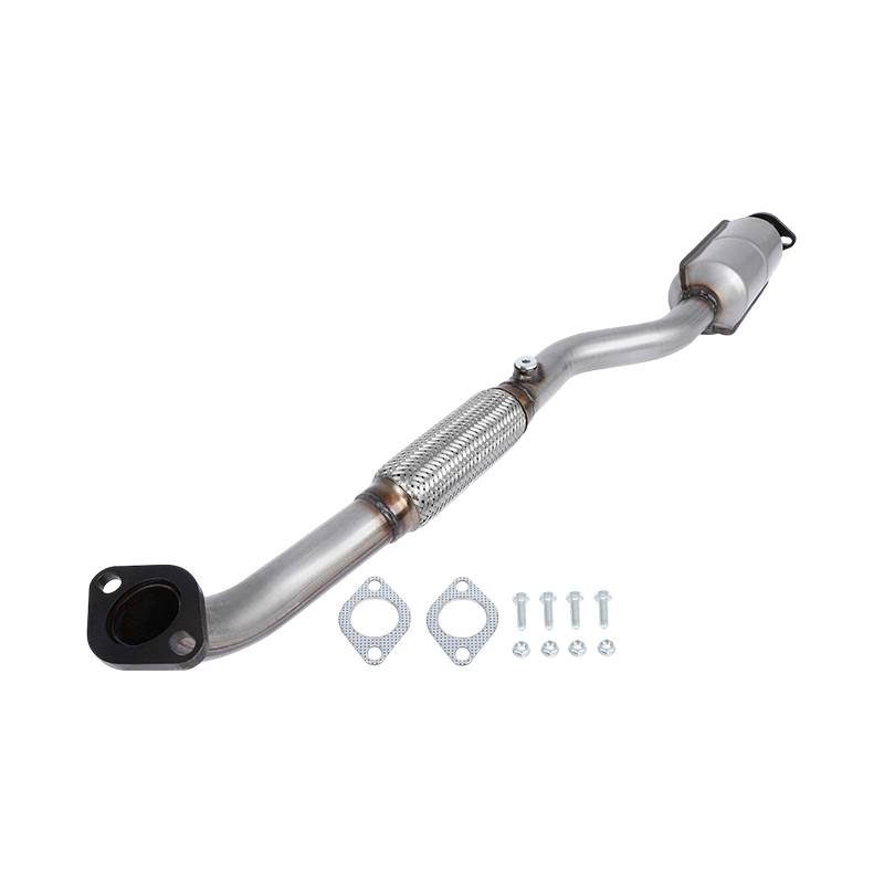
This product is designed for vehicles equipped with a 2.0L engine and an exhaust system OE number of 54774, applicable to 2004-2006 model years. It is...
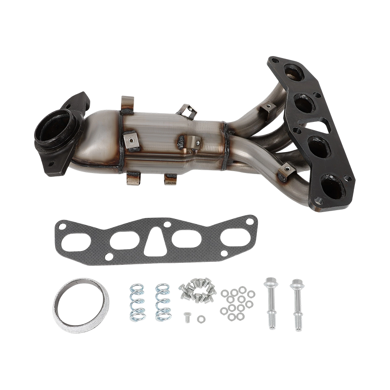
This product is designed for vehicles equipped with a 2.5L engine and an exhaust system OE number of 674-659, applicable to 2002-2006 model years. It ...
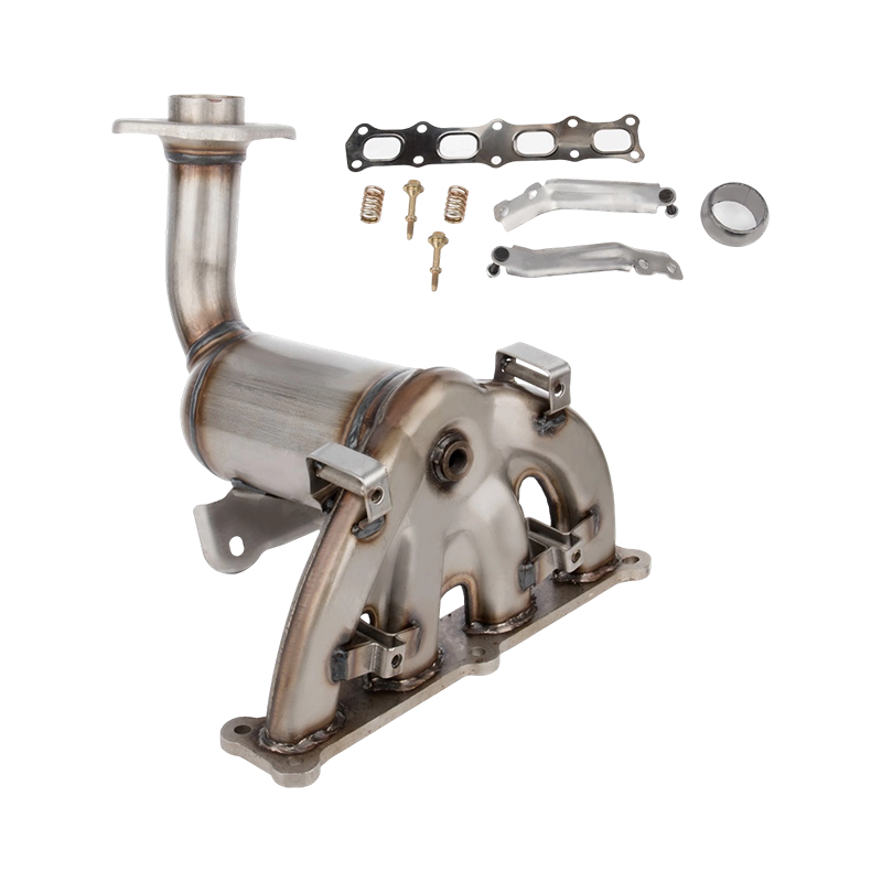
This product is designed for vehicles equipped with a 2.4L AWD engine and an exhaust system OE number of 674-871, applicable to 2007-2010 model years....
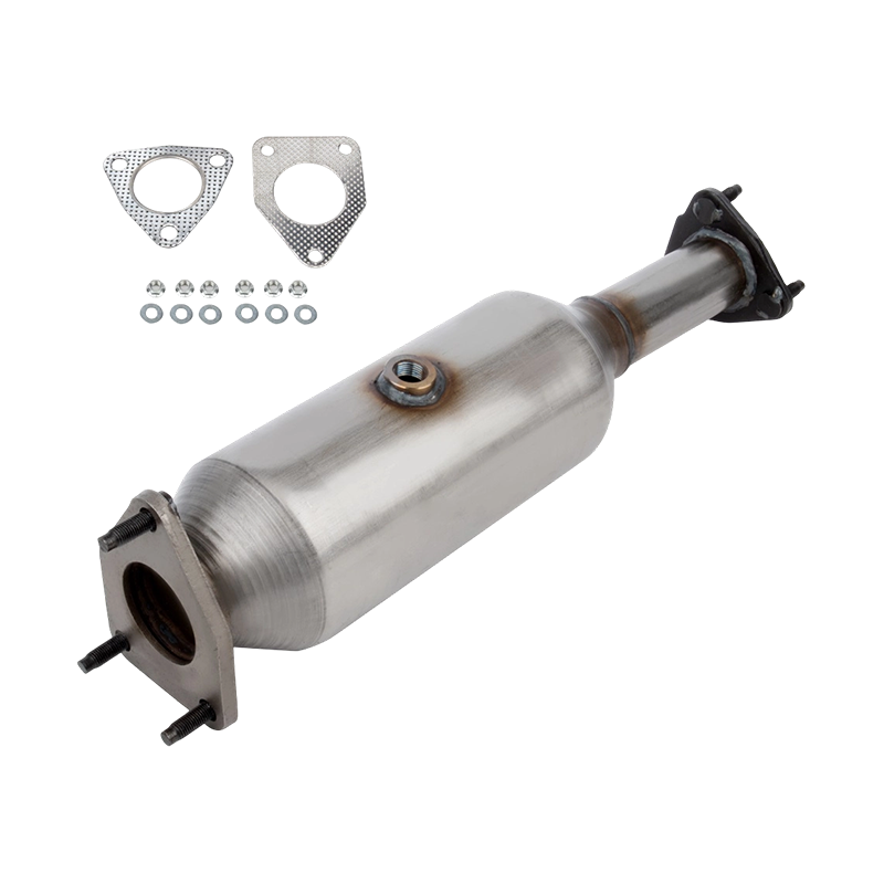
This product is designed for vehicles equipped with a 2.4L engine and an exhaust system OE number of 16299, applicable to 2003-2007 model years. It is...
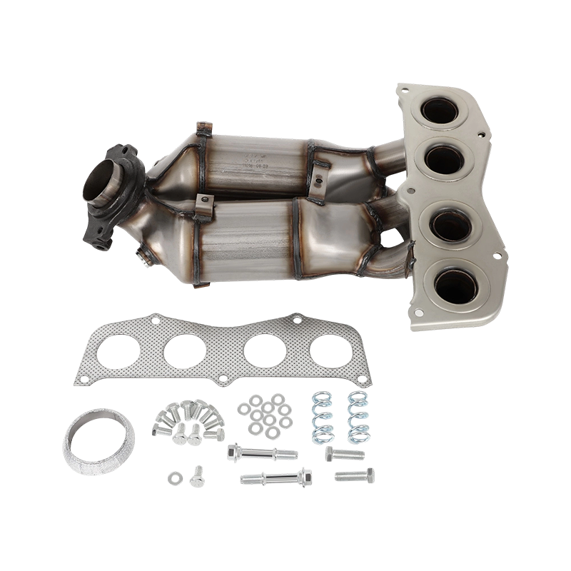
This product is designed for vehicles with an exhaust system OE number of 40583, applicable to 2001-2003 model years. It is an integrated assembly com...
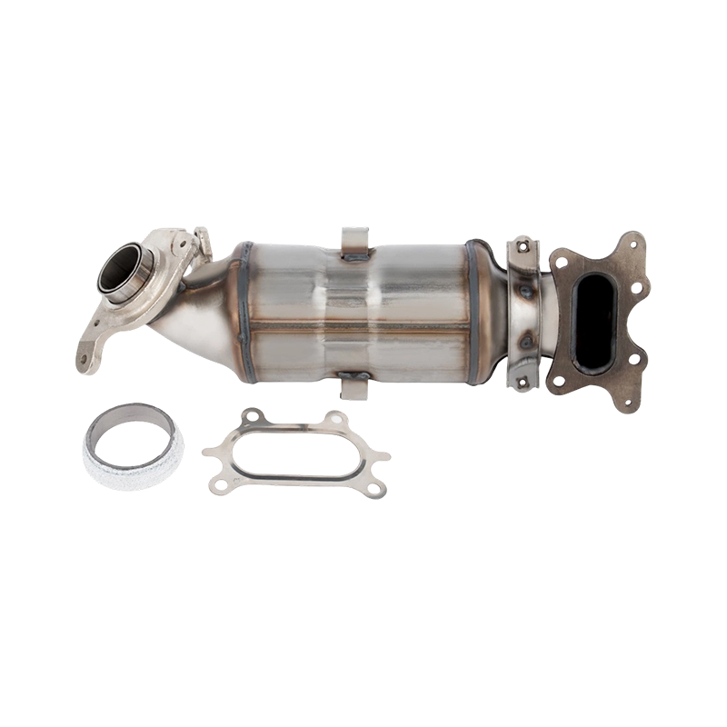
This product is designed for vehicles equipped with a 1.8L four-cylinder SOHC engine and an exhaust system OE number of 674-986, applicable to 2006-20...
Achieving structural integrity and optimal exhaust flow in emission control hardware depends entir......
READ MOREWhy Welded Catalytic Converter Components Matter in Modern Exhaust Systems Welded catalytic convert......
READ MOREMitigating hazardous exhaust emissions from internal combustion engines requires an exhaust treatme......
READ MOREWhen an exhaust system integrator or procurement engineer evaluates a catalytic converter, the firs......
READ MOREA DPF anti-corrosion filter is built with coated or treated materials to resist rust and chemical ......
READ MOREExhaust System Components The shell rarely fails first — but when it does, everything inside it goe......
READ MORE